
PP-17WH
MULTI-LEVEL PARKING LIFT
Offside Runway. The other Runway. It does not have a Hydraulic Cylinder or Cables under it.
Flex Tubes. Not shown. A flexible, black tube that attaches to an opening on the Powerside Runway on one end and to the Power Unit on the other end. Used for protecting the Return Line, Air Line, and Hydraulic Hose (and Microswitch Cable for Upper Platform) as they are routed to the Power Unit. One Flex Tube per Platform.
- Power Support Column The main column for mounting the power unit. The hydraulic power unit is fixed on one of its mounting brackets.
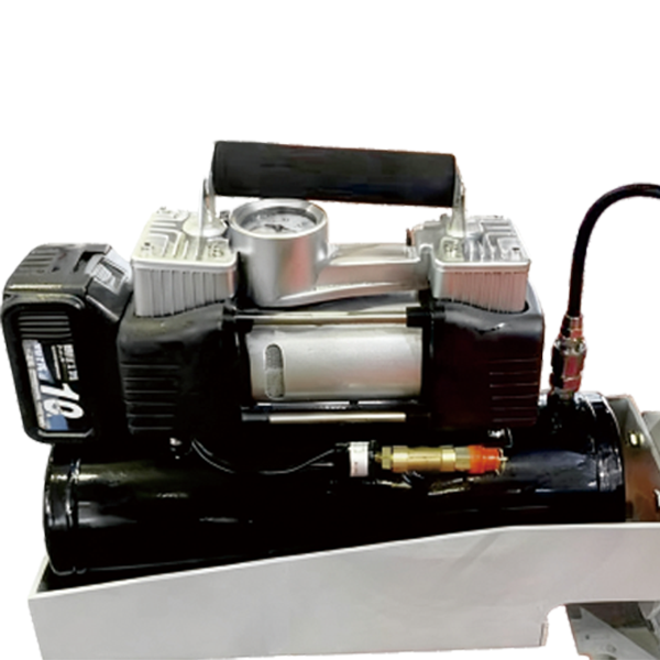
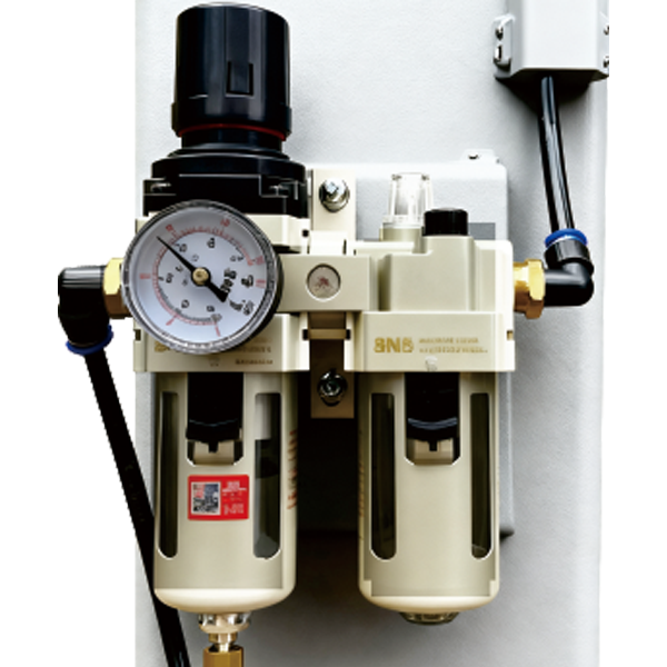
- Power Unit An electro/hydraulic device connected to an electrical power source. It supplies hydraulic oil to the cylinders to drive the lifting and lowering of the platforms.
- Flexible Fire-Resistant Protective Cloth A flexible black fire-resistant cloth attached to the runway on the power side and the power unit on the other end. It protects the return oil hose, air hose, hydraulic hose (as well as the micro-switch cables of the upper platform) as they are guided toward the power unit. One protective cloth is used per platform.
- Upper Platform Capable of supporting vehicles up to 8,000 lbs (3,600 kg).
- Lower Platform Capable of supporting vehicles up to 9,000 lbs (4,000 kg).
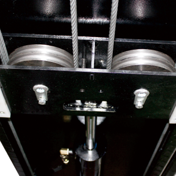
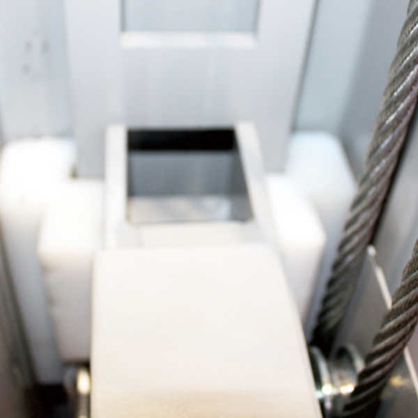
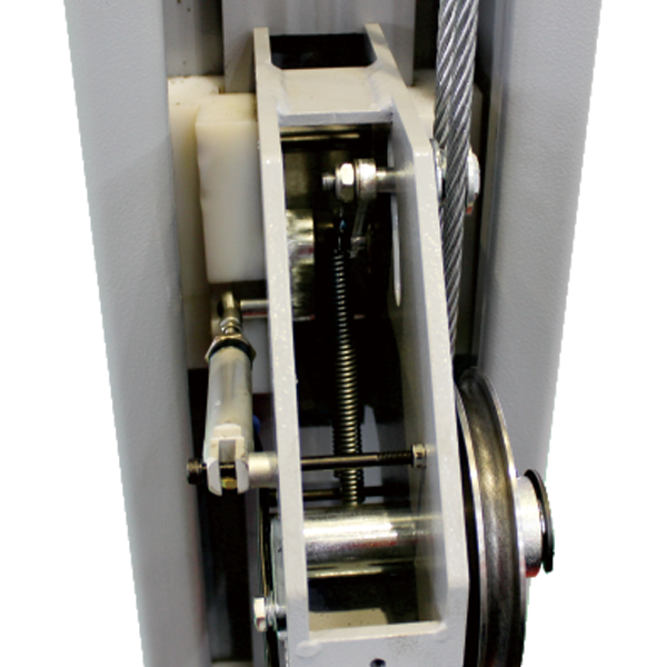
- Power-Side Platform The power-side platform and the supporting power column are on the same side (where the power unit is installed). Below the power-side platform are the drive hydraulic cylinders, steel cables, and rotating wheels. The transmission steel cables of the upper and lower power platforms are different.
- Non-Power-Side Platform No hydraulic cylinder or steel cable is installed underneath, and the upper and lower platforms are identical.
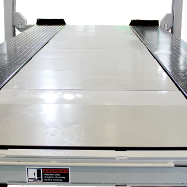
- Intermediate Drip-Proof Plates Installed between the two runways on both upper and lower platforms to prevent liquid leakage from dripping onto vehicles below. Each level contains nine plates. Standard material is iron; aluminum plates are available upon request.
- Safety Limit Stop Bar Located beneath the upper platform. The stop bar prevents the lift from rising further. If you are lifting a vehicle located on the lower platform and the vehicle hits the safety stop bar, the lift will stop operating immediately to ensure operational safety.
- Front and Rear Cross Beams Provide additional structural strength to the lift. Two beams connect to the power-side support column, and the other two connect to the non-power-side support column.
- Drive-on Ramps The upper platform is equipped with longer, foldable ramps, while the lower platform uses shorter ramps. They allow vehicles to drive onto and off the platform. Each platform is equipped with two ramps.
- Wheel Stops Installed at the front end of the lift to prevent the front wheels from rolling forward. The rear wheels are secured with rubber wedges. Four wedges are provided for each platform.
- Safety Locks When the system is activated, the safety locks prevent the platform from descending in case of power failure or hydraulic leakage. Each support column contains a row of safety locking ladders with locking holes spaced 3.94 inches (100 mm) apart, enabling the platform to be locked at various heights within the lifting range. An optional slack-cable safety system is available, and the lift must be fully lowered to the ground or locked before the operator leaves the equipment.
- Hydraulic Selector Valve Controls the vertical lifting motion of the upper and lower platforms. Only one platform can be lifted or lowered at a time.
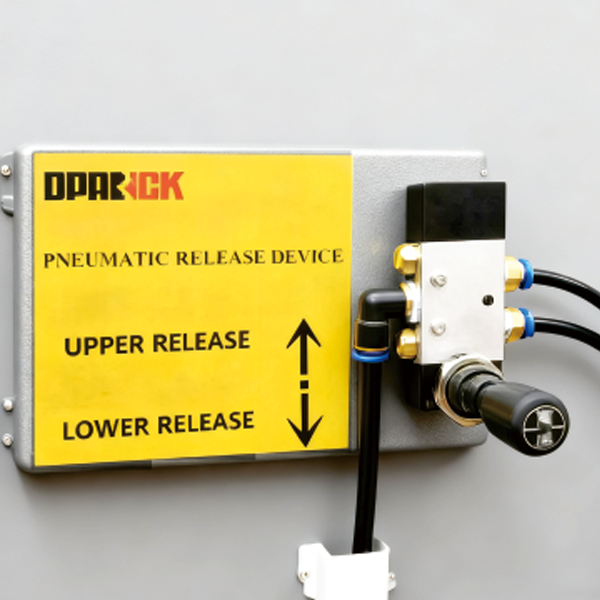
- Air-Actuated Unlocking Valve Raise the selected platform by approximately 60mm to disengage the safety lock block inside the cross beam from the safety lock ladder hole inside the support column. Then, switch the unlocking air valve so that it does not engage when the elevator descends, thus lowering the platform.
- This product is a specialized piece of equipment. It must only be operated by personnel who have received proper training or have thoroughly read and understood the operation manual. Failure to do so may lead to safety hazards and accidents.
 Product Technical Parameters
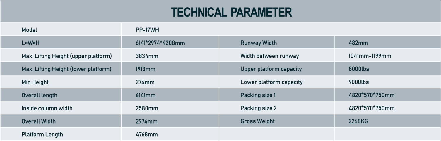
 Outline dimension drawing of product
.jpg)
 Description of product details and features
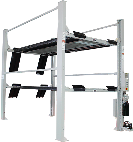
 Product rolling jack and configuration
RJ4500(002)
MANUAL ROLLING JACK
4,500-lb. Capacity / Rolling Bridge Jack
 Product video operatoin demonstration
Catalogs Download


Quotation list
Operation Video


